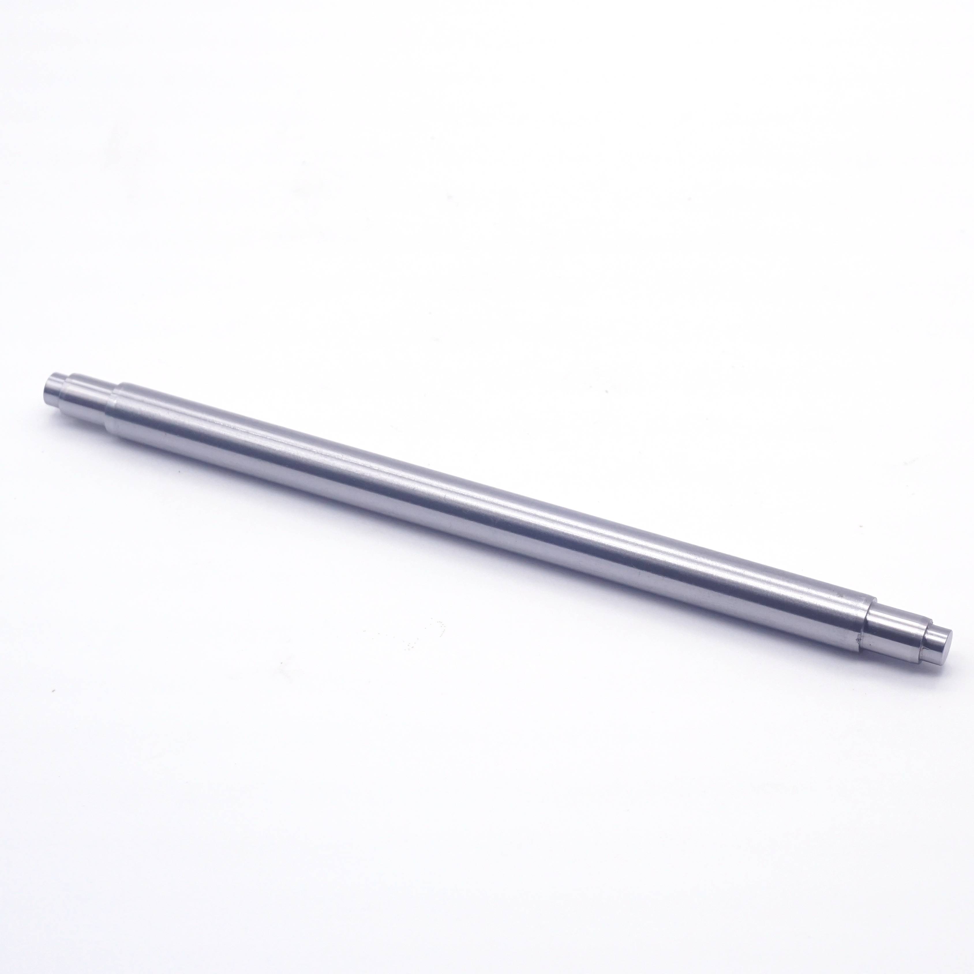
Precision alignment in mechanical assemblies relies entirely on the mathematical relationship between a locating pin and its mating hole; treating this as an afterthought guarantees assembly failure. Specifying incorrect dowel pin sizes or tolerances leads to critical manufacturing issues, including component galling, cracked housings, loss of positional repeatability, and costly production downtime. When parts shift under load, the entire machine geometry fails. You cannot rely on bolts for alignment. Bolts secure components together, but pins dictate their exact location.
Navigating the technical evaluation requires a strict understanding of standard specifications (ASME/DIN), interference fit calculations, material hardness variables, and knowing when to transition from off-the-shelf components to custom engineered solutions. You must evaluate shear loads, host material yield strength, and insertion methods before finalizing your CAD models. This guide provides the exact engineering parameters needed to specify the correct pins, ensuring your assemblies remain rigid, accurate, and repeatable under heavy industrial use.
Tolerance Dictates Function: The choice between standard, oversized, and undersized pins determines whether the pin acts as a permanent fixture (press fit) or a removable alignment tool (slip fit).
Mating Material Matters: The hardness, weight, and shape of the host material directly influence the required hole size and pin material; softer housings require different engagement strategies than hardened steel.
Standard vs. Custom: While standard ASME/DIN sizes cover 80% of applications, high-stress or unique environmental conditions often necessitate custom metal locating pins.
Vetting is Critical: Partnering with a verified dowel pin manufacturer ensures lot-to-lot consistency, which is mandatory for automated, high-volume assembly lines.
Understanding Standard Dowel Pin Sizes and Specifications
Nominal vs. Actual Dimensions
Engineers frequently confuse nominal size with actual manufactured size. The nominal size is simply the named dimension used for general classification on a print, such as a 1/4-inch or 6mm pin. The actual dimension is the physical measurement of the manufactured part. Standard pins are intentionally manufactured slightly oversized to guarantee a secure press fit in a nominally sized hole. A nominal 0.250-inch pin typically features a minimum diameter of 0.2501 inches and a maximum of 0.2503 inches. If a machinist reams a hole to exactly 0.2500 inches, the pin will press in tightly. Failing to account for this built-in oversize tolerance results in loose assemblies that vibrate apart or cracked host materials from excessive interference.
You must communicate these actual dimensions to the shop floor. Operators need to know the exact pin diameter to select the correct reamer. If you just call out a "1/4-inch hole" without a specific tolerance band, the operator might drill it to 0.250 inches, 0.255 inches, or 0.245 inches depending on the tooling available. This lack of control destroys assembly repeatability.
Utilizing a Dowel Pin Size Chart
You must consult a standardized size chart during the initial CAD phase. Do not guess the tolerances. A proper chart cross-references nominal sizes with the actual manufactured minimum and maximum diameters. It also provides the recommended hole sizes for both press fits and slip fits. Integrating this data early prevents costly rework. Machinists rely on these charts to select the correct reamer sizes. If your drawings lack specific tolerance callouts based on standard charts, you leave the fit up to the operator's discretion.
Nominal Size (Inch)
Standard Pin Actual Diameter (Min/Max)
Recommended Press Fit Hole Size
Recommended Slip Fit Hole Size
1/8" (0.1250")
0.1251" - 0.1253"
0.1245" - 0.1250"
0.1255" - 0.1260"
1/4" (0.2500")
0.2501" - 0.2503"
0.2495" - 0.2500"
0.2505" - 0.2510"
3/8" (0.3750")
0.3751" - 0.3753"
0.3745" - 0.3750"
0.3755" - 0.3760"
1/2" (0.5000")
0.5001" - 0.5003"
0.4995" - 0.5000"
0.5005" - 0.5010"
Fractional (Imperial) vs. Metric Dowel Pin Sizes
Fractional pins dominate legacy American manufacturing, with common sizes ranging from 1/16-inch to 1-inch in diameter. Metric pins, ranging from M1 to M30, are the global standard for modern equipment. Mixing metric and imperial specifications in global supply chains introduces massive engineering risks. A 6mm pin measures 0.2362 inches. If an operator forces a 1/4-inch (0.250-inch) pin into a 6mm hole, the host material will fracture immediately. Standardize your entire assembly on one measurement system to eliminate floor-level confusion.
Metric pins utilize the ISO tolerance system, commonly specifying m6 for standard press fits or h6 for slip fits. An m6 tolerance on a 10mm pin means the actual diameter will be between 10.006mm and 10.015mm. Understanding these specific tolerance bands is mandatory when designing equipment for international production facilities.
ASME and DIN/ISO Standards Overview
Standardization ensures predictable mechanical behavior across different production runs. ASME B18.8.2 governs unhardened ground pins primarily used in North America. DIN 6325 and ISO 8734 dictate the requirements for hardened precision pins used globally. Adhering to these standards guarantees baseline shear strength, material composition, and dimensional consistency. You cannot achieve repeatable assembly if you buy unrated pins from unverified sources.
DIN 6325 pins are case-hardened to 58-62 HRC, providing a tough inner core that resists shear forces and a hard outer shell that prevents wear during insertion. ASME pins offer more variety in material but often require specific callouts for hardening. Always specify the exact standard on your engineering drawings to prevent purchasing departments from substituting inferior hardware.
Determining the Right Precision Dowel Pin Dimensions for Your Application
The Three Core Factors of Hole Sizing
The required hole size depends on three interdependent variables. First, you must know the exact tolerance on the dowel itself. Second, you must define the tightness of the fit needed. A permanent fixture requires a press fit, while a removable alignment tool needs a slip fit. Third, you must evaluate the hardness of the mating components. You cannot press a hardened steel pin into a hardened steel block using the same interference margin you would use for cast aluminum.
Calculating Hole Size and Interference (Press Fit vs. Slip Fit)
Calculating interference fits requires precise math. To achieve a standard press fit, the hole must be slightly smaller than the pin's minimum diameter. Specifying accurate precision dowel pin dimensions ensures the parts assemble without excessive force while maintaining rigid alignment.
Determine the nominal pin size and locate its maximum actual diameter on a standard chart.
Identify the host material. Hard materials require less interference; soft materials require more.
For a press fit in steel, subtract 0.0005 inches from the nominal size to establish the target hole diameter.
For a slip fit in steel, add 0.0005 inches to the maximum actual pin diameter to establish the target hole diameter.
Specify the hole tolerance on the print, typically +0.0002 / -0.0000 inches, to ensure the machinist uses a precision reamer rather than a standard drill bit.
Component Weight, Shape, and Shear Load
The physical shape and total weight of the connected materials dictate the required pin diameter. Pins fail under shear load, not tensile load. Dynamic loads and heavy vibrations amplify shear forces exponentially. If you connect two massive steel plates subject to lateral impact, a 1/8-inch pin will shear instantly. Calculate the maximum anticipated shear force and select a diameter that offers a safety factor of at least 3:1. Distribute the load across multiple pins rather than relying on a single large dowel.
When calculating shear strength, you must account for the pin's cross-sectional area and the material's ultimate shear strength. A 1/4-inch alloy steel pin typically handles around 7,000 pounds of double shear load. A 1/2-inch pin of the same material handles over 28,000 pounds. Always verify these ratings with your supplier's technical data sheets.
The Role of Component Hardness in Sizing
Host material hardness changes everything. Softer materials like cast aluminum, brass, or industrial plastics require a larger interference margin. A standard 0.0005-inch press fit in aluminum will vibrate loose over time because the soft metal yields and deforms under load. You often need 0.001 to 0.002 inches of interference for soft housings. Conversely, pressing a pin into hardened tool steel requires a very tight tolerance margin. Too much interference in hardened steel will cause the pin to gall or the block to crack, as neither material will yield.
Length Selection and Engagement Ratios
Pin length is not arbitrary. Follow a strict rule of thumb: the pin should engage the host component by at least 1.5 to 2 times its own diameter. A 1/2-inch diameter pin needs at least 3/4 to 1 inch of embedment in the base block. Over-specifying length increases the risk of bending and shear failure, as the exposed pin acts like a lever. Under-specifying length compromises alignment integrity and allows the pin to wallow out the hole under vibration.
When joining two plates, the pin should press tightly into the thicker or stationary plate and slip-fit into the removable plate. The press-fit engagement should be longer than the slip-fit engagement to ensure the pin remains in the base plate during disassembly.
Material Selection and Manufacturing Approaches
Hardened Alloy Steel vs. Stainless Steel
Material selection dictates performance in harsh environments. Hardened alloy steel, such as 4140 or 8620, provides exceptional shear strength and wear resistance. It is the default choice for heavy machinery, stamping dies, and tooling fixtures. However, alloy steel rusts quickly in damp environments. Stainless steel, particularly 300 and 400 series, offers excellent corrosion resistance. The trade-off is strength. 300 series stainless (like 316 or 18-8) is softer and will shear under loads that 4140 would easily survive. 400 series stainless (like 416 or 440C) offers a middle ground, providing moderate corrosion resistance and the ability to be heat-treated for higher hardness.
Material Type
Corrosion Resistance
Shear Strength
Best Application
Alloy Steel (Hardened)
Low
Very High
Heavy machinery, dies, indoor fixtures
316 Stainless Steel
Very High
Low to Moderate
Marine, food processing, medical devices
416 Stainless Steel
Moderate
High (Heat Treatable)
Outdoor equipment, moderate load assemblies
Brass Knurled Dowel Pin Applications
Smooth pins fail in plastics and die-cast metals. They either slip out under vibration or crack the brittle housing during insertion. This is where a brass knurled dowel pin becomes necessary. The knurled texture features raised ridges that displace the soft host material during insertion. This creates a mechanical interlock, providing a secure hold without requiring extreme press-fit tolerances. Brass also resists corrosion and prevents galvanic reactions when paired with aluminum housings.
Knurled pins come in straight, helical, or diamond patterns. Straight knurls resist rotational forces, making them ideal for pivot points. Helical knurls twist as they are pressed in, providing excellent pull-out resistance. Diamond knurls offer a combination of both, locking the pin firmly in all directions within a plastic or cast housing.
CNC Machined Dowel Pins for Tight Tolerances
Standard centerless grinding works well for basic cylindrical pins. However, modern assemblies often require complex geometries that grinding cannot achieve. You need CNC machined dowel pins when your design calls for stepped diameters, tapped extraction holes, or specific micro-finishes. CNC turning centers hold tolerances down to tenths of a thousandth of an inch while simultaneously cutting chamfers and grooves in a single setup. This eliminates secondary operations and ensures perfect concentricity across multiple diameters.
Machining also allows for custom material selection. If your application requires a specific aerospace alloy like Inconel or Titanium, standard catalog pins will not exist. CNC machining provides the flexibility to produce exact alignment components from any machinable metal.
Evaluating Custom Metal Locating Pins vs. Off-the-Shelf Options
When Standard Sizes Fall Short
Standard catalog pins cover the majority of basic assembly tasks. Yet, specialized manufacturing scenarios frequently push standard components past their breaking point. Extreme temperature environments cause atypical thermal expansion, causing standard pins to seize or fall out. Proprietary assembly equipment often requires non-standard lengths or unique head profiles. When you face these constraints, forcing a standard pin into a non-standard application guarantees failure.
Consider an engine block assembly operating at high temperatures. The aluminum block expands faster than a standard steel pin. A custom pin machined from a material with a matching coefficient of thermal expansion prevents the joint from loosening during operation.
Trade-offs: Lead Time and Application Specificity
Choosing between standard and custom parts involves balancing immediate needs against long-term reliability. Standard pins offer immediate availability. You can order them by the thousands for next-day delivery. Custom designs require engineering time, machine setup, and longer lead times. However, specifying custom metal locating pins drastically reduces assembly failure rates in specialized machinery. The upfront investment in custom machining pays off by eliminating warranty claims and field service repairs caused by sheared or loose alignment pins.
Specialized Features for Industrial Positioning
Custom pins allow for critical modifications. Vented pins feature a flat milled along the side to release trapped air in blind holes. Bullet-nose chamfers enable smooth, jam-free insertion for robotic assembly arms. Internal threads allow technicians to extract the pin easily using a slide hammer during maintenance. Integrating these features into an industrial positioning dowel pin transforms it from a simple fastener into a highly engineered alignment system.
Stepped pins are another common custom feature. They feature a larger diameter on one end for a heavy press fit and a smaller diameter on the other for a precision slip fit. This prevents the pin from being pushed entirely through a through-hole during heavy lateral impacts.
Implementation Risks: Common Sizing and Installation Failures
Galling and Material Deformation
Galling is a form of severe adhesive wear. It occurs when two metal surfaces fuse together under extreme pressure. Forcing an oversized pin into an improperly toleranced hole without lubrication causes galling instantly. The metals tear, creating jagged burrs that lock the pin in place before it reaches its full depth. You must control hole tolerances strictly, specify proper surface finishes, and apply anti-seize compounds during assembly to prevent this failure.
Stainless steel is particularly susceptible to galling. When pressing a stainless pin into a stainless block, the friction strips the protective oxide layer, causing the raw metals to cold-weld. Always use a dissimilar metal or a heavy-duty assembly lubricant when working with stainless steel alignment components.
Blind Hole Trapped Air (Pneumatic Lock)
Pressing a tight-fitting pin into a blind hole creates a pneumatic cylinder. The trapped air compresses at the bottom of the hole. Once the insertion press releases, the compressed air forces the pin back out. This pneumatic lock ruins assembly tolerances. Mitigate this risk by specifying flat-sided or grooved pins. These modifications provide an escape path for the air, allowing the pin to seat fully and remain in position.
If you cannot use a vented pin, you must drill a small cross-hole into the bottom of the blind hole to allow the air to escape. This adds a machining step to the host block but guarantees the pin will not back out after installation.
Mitigation Strategies for High-Volume Assembly
Automated assembly lines magnify installation errors. A slight misalignment during robotic insertion will snap a pin or destroy the host block. Implement strict best practices to protect your production volume.
Verify chamfer angles on all incoming pins to ensure they guide smoothly into the holes without catching the edge.
Control the insertion force using servo-driven presses equipped with load cells. If the force spikes, the press stops before causing damage.
Implement inline optical measurement systems to verify pin depth and presence before the assembly moves to the next station.
Use vibratory bowl feeders with orientation traps to ensure pins are always fed chamfer-down into the insertion head.
How to Vet a Dowel Pin Manufacturer
Quality Control and Tolerance Verification
You cannot verify tolerances with cheap calipers. Precision pins require advanced metrology. When selecting a dowel pin manufacturer, demand comprehensive quality control documentation. Request First Article Inspection (FAI) reports and Production Part Approval Process (PPAP) documentation. The supplier must prove they use laser micrometers and optical comparators to hold dimensional tolerances down to +/- 0.0001 inches. If they cannot provide this data, they cannot guarantee the fit.
Ask to see their gauge calibration records. A supplier claiming to hold tenths of a thousandth of an inch must have their measurement equipment calibrated regularly by a certified third-party lab. Without this traceability, their inspection reports are meaningless.
Production Capacity and Material Traceability
A supplier might produce ten perfect prototypes but fail completely on a 50,000-piece run. Evaluate their ability to scale production without suffering tolerance drift. Machine tool wear causes parts to grow larger over time; the manufacturer must have processes to compensate for this automatically. Furthermore, demand raw material traceability. Aerospace, automotive, and medical applications require DFARS compliance and strict material certs. You must know exactly what alloy went into your pins and where that steel was poured.
Conclusion
Review your assembly CAD models to ensure hole tolerances match standard pin oversize dimensions.
Calculate the maximum anticipated shear loads to determine the correct pin diameter and material hardness.
Specify vented flats for all blind hole applications to eliminate pneumatic lock risks.
Request First Article Inspection reports and material certs from your supplier before initiating full-scale production.
FAQ
Q: What is the standard tolerance for a precision dowel pin?
A: Standard precision ground pins typically hold a tolerance of +/- 0.0001 inches. This tight variance ensures predictable interference fits. You must machine your mating holes with equally tight tolerances, usually requiring a precision reaming operation after drilling.
Q: How much oversized should a dowel pin be for a press fit?
A: Standard pins are manufactured 0.0001 to 0.0003 inches over their nominal diameter. For a standard press fit in steel, the hole should be reamed approximately 0.0005 inches undersized relative to the pin's nominal dimension.
Q: What is the difference between an oversized and undersized dowel pin?
A: Oversized pins are designed for permanent press fits, locking tightly into the host material. Undersized pins are slightly smaller than nominal and are used for slip fits, allowing for precise alignment in assemblies that require frequent disassembly.
Q: How do you measure precision dowel pin dimensions accurately?
A: Standard hand calipers are insufficient for measuring tenths-of-a-thousandth tolerances. You must use calibrated micrometers, optical comparators, or laser micrometers to accurately verify the diameter and concentricity of a precision pin.
Q: When should I use a brass knurled dowel pin instead of smooth steel?
A: Use brass knurled pins in plastics, 3D printed parts, and soft cast metals. The knurled ridges displace the soft material to create a mechanical lock. A smooth steel pin would easily slip out or crack the brittle housing during insertion.
Q: What is an industrial positioning dowel pin used for?
A: It aligns heavy machine components, secures gearboxes, and maintains strict positional accuracy between mating parts. It absorbs lateral shear forces and prevents components from shifting under heavy vibration or dynamic loads.
Q: Can I use standard drill bits to create holes for dowel pins?
A: No. Standard drill bits wander and create holes that are slightly oversized and out of round. You must drill the hole slightly undersized and then use a precision reamer to achieve the exact diameter and surface finish required for a proper fit.