Specifying tighter tolerances does not automatically produce a better part. A dimension that controls a bearing fit, sealing surface, or locating feature may need close limits, while a cosmetic edge or clearance pocket often does not. Applying the same tolerance across every feature can raise machining and inspection costs without improving performance.
For custom CNC machined parts, the practical challenge is deciding where precision protects function and where general tolerances are sufficient. The following sections explain how to evaluate mating conditions, choose dimensional and geometric controls, account for material and finishing effects, and communicate requirements clearly to the manufacturer.
Begin with the Fit the Part Has to Achieve
Separate Critical Dimensions from Ordinary Geometry
Start by asking what would fail if a dimension moved toward either end of its permitted range. That question separates critical features from geometry that merely defines the part’s shape. Bearing seats, locating bores, sealing faces, shoulders, hole patterns, and threaded engagements often control function or assembly, while clearance pockets, cosmetic edges, and unrestricted exterior surfaces may only need general tolerances.
Classify the dimensions on custom CNC machined parts as critical to function, critical to assembly, or non-critical. The category must depend on the feature’s real role, not its appearance on the CAD model. A bore may locate precisely on a pin in one design but simply provide screw clearance in another.
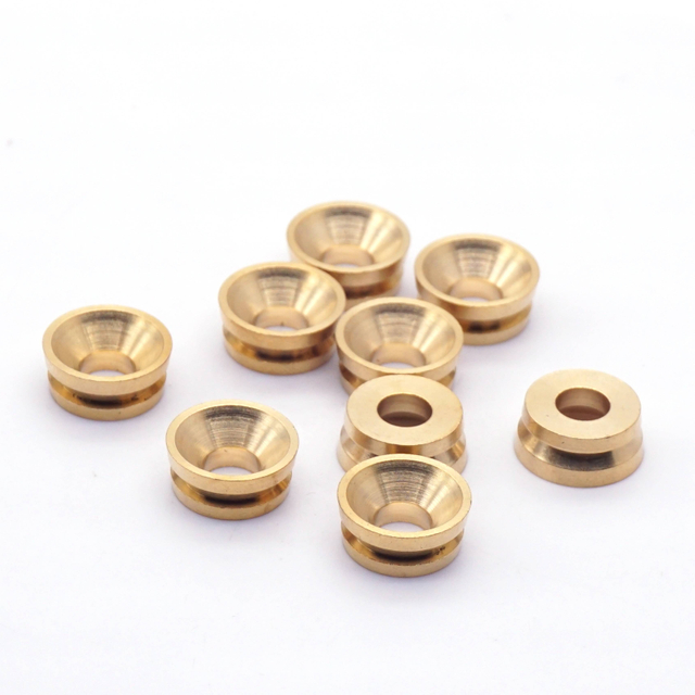
A brass spacer illustrates the difference. Its height may establish component separation or preload, its bore may locate on a pin, and its outside diameter may matter only when it enters a counterbore. For a customizable Hanyee Metal CNC-machined brass spacer, the outside diameter, bore, and height can each be specified according to their assembly purpose rather than controlled by one blanket tolerance.
Work Backward from the Complete Assembly
Choose tolerances for custom CNC machined parts from the required assembly result, not from an isolated component. Begin with the maximum acceptable variation in clearance, interference, alignment, or axial position, then work backward through every contributing dimension. This tolerance-stack review shows where precision is necessary and where manufacturing flexibility remains.
A shaft and bore may each pass inspection yet fail to assemble if their limits do not create the intended fit. Several acceptable spacer, washer, housing, and shoulder dimensions can also accumulate into excessive end play or unintended preload. Operational temperature, load deflection, and lubricant clearance should be included where they affect the working condition.
Design changes can sometimes solve the problem more effectively than tighter values. A locating boss can separate positioning from fastening, a larger clearance hole can prevent bolt-pattern interference, and a stable datum can create a common machining and inspection reference for custom CNC machined parts.
Assign Tolerances Feature by Feature
Let General Tolerances Cover Non-Critical Dimensions
A drawing-wide general tolerance for custom CNC machined parts avoids repeated callouts on dimensions that do not need special control. ISO 2768-1:1989 covers general tolerances for linear and angular dimensions without individual tolerance indications. It provides four tolerance classes for workpieces produced through processes such as metal removal and sheet-metal forming.
The drawing should name the standard, revision, and class rather than saying only “standard tolerance.” Material, nominal size, geometry, process, and supplier capability still determine whether that class is economical for particular custom CNC machined parts.
Match the Tolerance Format to the Design Need
Use the callout that describes the functional boundary most clearly. Bilateral tolerances permit variation on both sides of nominal, unilateral tolerances allow it in one direction, and limit dimensions state the acceptable maximum and minimum directly. Fit systems are usually clearer for shafts and bores, while threads should be defined by the applicable form, class, and engagement depth.
On custom CNC machined parts, extra decimal places do not explain design intent. Dimensional tolerance controls size, GD&T controls form or relationships, and surface roughness controls texture. A bore can meet its diameter requirement while being misplaced, and a sealing face can meet its thickness requirement while remaining too rough to seal.
Avoid One Tolerance for the Entire Component
Use the feature’s function to select the control:
Feature
Main requirement
Suitable control
Bore or outside diameter
Location, rotation, or press fit
Size tolerance or fit system
Spacer height or shoulder
Axial position or preload
Individual linear tolerance
Hole pattern
Alignment with a mating part
Basic dimensions and position
Thread
Engagement and retention
Thread class and depth
Sealing face
Contact and leakage control
Flatness and surface finish
Exterior profile
Installation envelope
General tolerance or profile
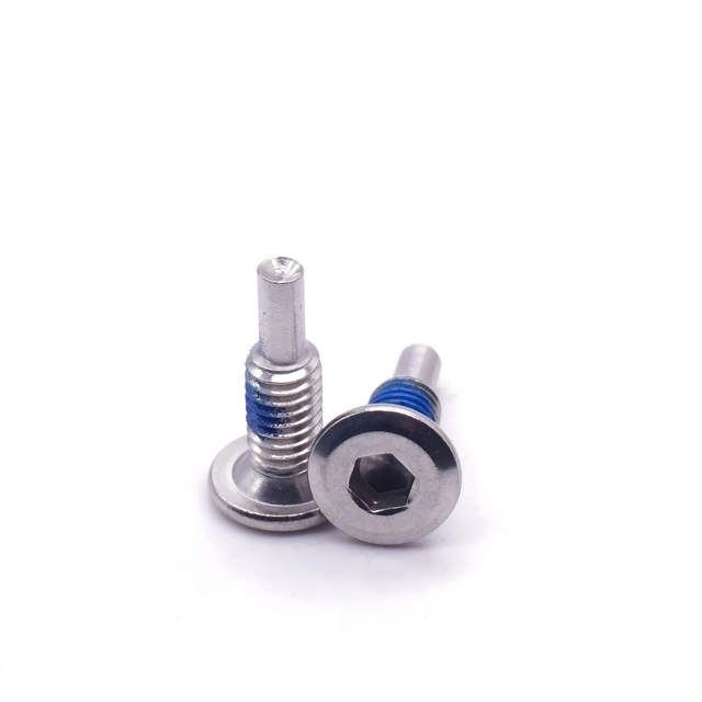
The brass spacer shows why bore, outside diameter, and height may need different values. A CNC-machined step screw has another hierarchy: stepped diameters may locate it, shoulder length may control clamping distance, and the thread must provide engagement. A Hanyee Metal custom step screw with a nylon patch uses the patch to support locking, but this feature does not replace proper control of the screw’s machined geometry.
Use GD&T When Feature Relationships Matter
Build the Datum Scheme Around Real Assembly Contact
Many custom CNC machined parts depend more on feature relationships than on individual sizes. A hole pattern must align with a mounting face, a shoulder may need to remain square to a shaft axis, and several diameters may need to rotate from one centerline. These conditions require a functional datum scheme.
Select datums from the surfaces or axes that locate the component in service. A primary mounting face can establish the first plane, a bore or shaft can define the main axis, and a secondary face or slot can prevent rotation. Stable, accessible references allow machining and inspection teams to reproduce the same setup.
Avoid flexible tabs, rough stock surfaces, or inaccessible edges as primary datums. Each reference should remove a clear degree of freedom without duplicating restraints already established elsewhere.
Apply Only the Controls That Protect Function
Position controls the permitted location of holes or pins relative to datums. Perpendicularity protects shoulder or face orientation, flatness controls the form of one surface, runout limits variation around a datum axis, and profile can define complex contours. These controls should be used only where they protect fit, movement, sealing, or interchangeability.
ASME Y14.5-2018, reaffirmed in 2024, establishes standardized symbols, definitions, rules, defaults, and recommended practices for dimensioning and tolerancing on engineering drawings and digital product definitions. A bolt-hole pattern, for example, can often be defined more functionally with basic dimensions and position tolerance than with separate plus-or-minus coordinates.
More symbols do not make custom CNC machined parts better specified. Avoid redundant combinations of flatness, parallelism, profile, and runout, and do not choose datums that cannot be inspected consistently. The drawing should also identify whether ASME or ISO conventions govern rather than mixing systems without clarification.
Check What the Material and Process Can Actually Hold
Account for Material and Part Geometry
The same tolerance can be routine on a short, rigid turned diameter and difficult on a long, flexible feature. Thin walls can deflect during clamping, deep bores restrict tool access, and small internal details may require delicate tooling. Interrupted cuts, uneven stock removal, and features machined across several setups add further variation.
Material hardness, machinability, thermal expansion, work hardening, flexibility, and residual stress also affect the result. A part may shift as it cools or as internal stress is released after machining. Tolerance feasibility should therefore be reviewed against the actual material, geometry, nominal size, production quantity, and inspection method for the custom CNC machined parts being ordered.
Consider Every Operation After Machining
For custom CNC machined parts, plating adds material, grinding and polishing remove it, and heat treatment can alter geometry. Deburring may change short shoulders, edge dimensions, or thread starts, while passivation has a different dimensional effect from a deposited coating. The drawing must state whether critical dimensions apply before or after finishing.
The Hanyee Metal C36000 brass spacer is available with nickel plating, gold plating, or passivation. When its bore, diameter, or height controls assembly, the inspection condition should be defined explicitly.
A nylon patch on a step screw should be specified separately by location and locking requirement. The machined shoulder, stepped diameters, and thread remain subject to their own dimensional and geometric controls.
Tighten Tolerances Only When the Benefit Justifies the Cost
Tighter requirements can change the manufacturing plan for custom CNC machined parts. They may require more precise fixturing, slower finishing cuts, tool-wear compensation, additional setups, grinding, or frequent in-process measurement. Inspection can also become a major cost when every component needs a CMM routine or specialized gauge.
Cost rises because the process must become more controlled, not simply because a smaller number appears on the drawing. A tolerance near the edge of process capability increases cycle time and scrap risk. Before tightening it, ask whether a wider range would reduce safety, service life, sealing, fit, motion quality, or interchangeability.
Early manufacturer review can reveal a more economical solution. A different datum strategy, machining sequence, fit class, or feature design may protect performance without overconstraining custom CNC machined parts.
Make the Drawing and Inspection Plan Unambiguous
Give the Manufacturer One Clear Source of Requirements
Supply a controlled 2D drawing with the 3D CAD model. The model defines geometry efficiently, while the drawing should record units, material, general tolerance standard, critical dimensions, datums, GD&T, threads, surface roughness, finishing condition, and revision status. State which document governs if they conflict.
Mark critical-to-quality characteristics so quotation, production, and inspection teams understand their priority. Avoid duplicate dimensions, conflicting callouts, unexplained extra decimal places, and notes such as “high precision throughout.” The release package for custom CNC machined parts should also state whether dimensions apply before or after coating and how burrs, edges, and threads will be accepted.
Clarity during quotation allows the manufacturer to plan tooling, setup, finishing, and measurement before confirming price and lead time. Requirements discovered after machining begins are more likely to cause delay, rework, or disagreement.
Agree on Measurement and Documentation Before Production
Use a pre-RFQ review:
●Which features control fit, motion, sealing, or alignment?
●What general tolerance covers the remaining dimensions?
●Have mating dimensions and tolerance stacks been checked?
●Are the datum features stable and measurable?
●Do dimensions apply before or after surface treatment?
●Which characteristics require first-article or batch reporting?
●Are material certificates, inspection reports, or PPAP documents required?
The measurement method for custom CNC machined parts must suit the requirement. Ordinary dimensions may be checked with conventional gauges, while position, profile, bore geometry, or runout may need optical equipment, functional gauges, or a coordinate measuring machine. Both parties should agree on datum simulation, sampling, rounding, and acceptance criteria before production.
Hanyee Metal can support material reports, inspection reports, PPAP documentation, and third-party testing when required. Buyers should include these records in the RFQ so the inspection workload is planned for the custom CNC machined parts rather than added at shipment.
Conclusion
Good tolerance decisions start with function, not the tightest value a machine can hold. General tolerances can cover non-critical dimensions, while fits, datums, GD&T, material behavior, surface treatments, and inspection methods should be defined only where they affect assembly or performance.
Ningbo Hanyue Metal Products Co., Ltd. supports custom CNC machined parts based on application requirements and technical drawings. By discussing critical dimensions, finishing conditions, and verification needs before production, buyers can reduce rework, control machining costs, and receive components that fit and perform as intended.
FAQ
Q: What is a standard tolerance for CNC-machined metal parts?
A: Standard tolerance varies by supplier, process, material, and feature size. General metal dimensions are often held less tightly than critical bores, shafts, sealing faces, or locating features.
Q: How tight should tolerances be on custom CNC machined parts?
A: Specify tight tolerances only where dimensional variation affects fit, motion, sealing, alignment, or safety. Non-critical surfaces and clearance features can usually follow the drawing’s general tolerance.
Q: Why do tighter CNC machining tolerances increase cost?
A: Tighter limits may require slower cutting, additional setups, specialized tooling, more frequent measurements, secondary finishing, and greater scrap control, increasing both machining time and inspection effort.
Q: Does material choice affect achievable CNC tolerances?
A: Yes. Hardness, thermal expansion, flexibility, work hardening, and internal stress influence dimensional stability. Thin or flexible parts may also move during clamping, machining, or inspection.
Q: When should GD&T be used instead of dimensional tolerances?
A: Use GD&T when function depends on feature relationships, including hole position, surface orientation, flatness, profile, or runout relative to defined datum features.
Q: How should tolerance requirements be communicated to a CNC manufacturer?
A: Provide a controlled 2D drawing with critical dimensions, general tolerances, datums, GD&T, thread specifications, surface finish, material, coating condition, and agreed inspection requirements.