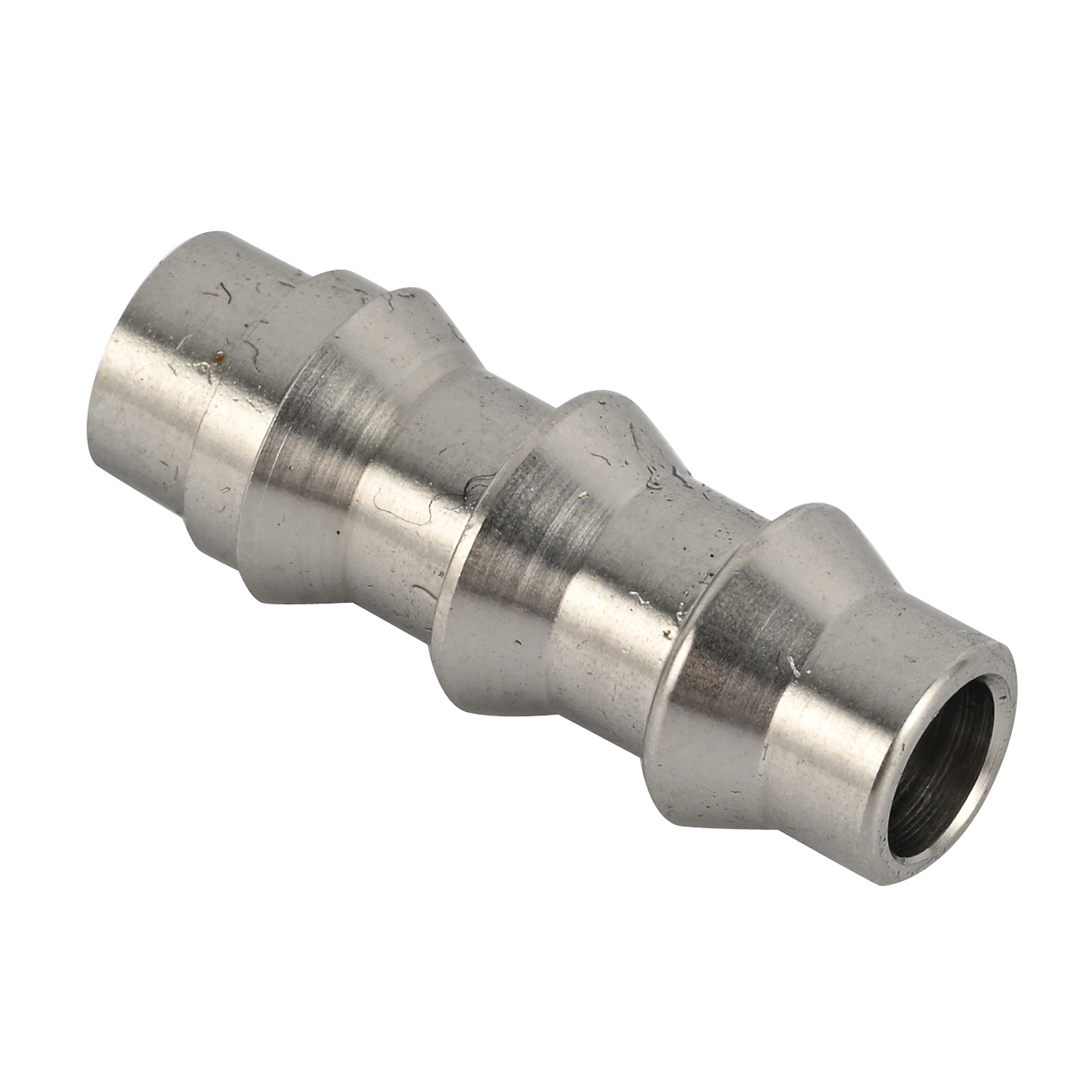
Manufacturing micro-components carries a disproportionately high cost of failure. A dimensional deviation of just a few microns can lead to catastrophic assembly failures in aerospace systems, medical devices, or advanced electronics. Scaling the production of highly complex, miniature geometries without sacrificing tight tolerances, surface finish, or unit economics is a massive engineering hurdle. Standard machining approaches routinely fail at the micro-level. Distinct physical and mechanical constraints dictate how small parts behave under cutting loads.
Successfully sourcing these components requires moving far beyond basic vendor capabilities. You must critically evaluate how a manufacturing partner handles specific micro-machining challenges. Everything from advanced workholding strategies to thermal management dictates the final yield. Buyers and engineers must align on the physical realities of micro-cutting to secure a reliable supply chain.
Key Takeaways
Physics Change at the Micro-Level: Tool pressure, vibration, and thermal expansion disproportionately affect small parts, requiring specialized equipment rather than scaled-down conventional processes.
Workholding is the Primary Bottleneck: Preventing component deformation while maintaining rigidity during multi-axis operations is the defining factor in yield rates for miniature components.
Swiss Machining is Often Mandatory: For length-to-diameter ratios exceeding 3:1, traditional turning introduces unacceptable deflection, making Swiss-style lathes the baseline requirement.
Vendor Metrology Dictates Quality: A partner’s ability to manufacture ultra precision miniature components is only as good as their ability to measure them; advanced optical and tactile metrology is a non-negotiable evaluation criterion.
The Physical Realities of Precision CNC Turning at the Micro-Scale
The Disproportionate Impact of Cutting Forces
Standard cutting tool pressures cause immediate deflection in small-diameter stock. When a tool engages a workpiece, it exerts both tangential and radial forces. On a large steel shaft, radial force is easily absorbed by the material's mass. On a micro-component, that same radial force pushes the material away from the cutting edge. This deflection results in tapered profiles, poor surface finishes, and dimensional inaccuracies. Managing this requires a deep understanding of tool geometry. Tool sharpness directly dictates the amount of cutting pressure generated. Dull tools rub rather than cut, spiking radial pressure and instantly bending the stock.
Feed rates must be perfectly synchronized with spindle speeds to maintain structural integrity. Pushing a tool too aggressively through a small diameter risks snapping the part entirely. You must balance material removal rates with the physical limits of the stock. Effective precision CNC turning relies on specialized inserts with positive rake angles and minimal edge honing. These tools shear the material cleanly, reducing the forces that threaten to distort the component during aggressive material removal phases. Machinists often utilize ground-up carbide inserts with nose radii as small as 0.05mm to minimize tool pressure on delicate features.
Thermal Dynamics and Dimensional Variation
Small parts possess minimal thermal mass. Heat generated at the cutting edge rapidly permeates the entire component. In macro-machining, the bulk of the part acts as a heat sink, drawing temperature away from the critical surfaces. Micro-components lack this capacity. The rapid heating leads to immediate thermal expansion during the machining cycle. A part may measure perfectly within tolerance while hot inside the machine enclosure. Once it cools to room temperature, it shrinks and fails final inspection.
Controlling this thermal dynamic requires high-pressure, temperature-controlled coolant systems. Vendors must flood the cutting zone with chilled cutting fluids to evacuate heat instantly through the chips, rather than allowing it to soak into the workpiece. Straight cutting oils are often preferred over water-soluble coolants in micro-applications because they provide superior lubricity, which prevents built-up edge (BUE) on micro-tools. Without this infrastructure, holding tight tolerances across a long production run becomes physically impossible due to continuous thermal drift.
Material Selection: The "Machinability" Factor
Material selection heavily dictates the success of micro-machining operations. Free-machining alloys contain additives like sulfur or lead. These additives help chips break cleanly, reducing cutting friction and heat. They are ideal for miniature geometries. Conversely, challenging materials present severe hurdles. Pure copper is gummy and prone to tearing, while titanium tends to work-harden instantly if the tool rubs instead of cutting.
Machining these difficult alloys requires highly specific tool geometries, rigid setups, and optimized speed-feed combinations. If a vendor treats titanium like brass, they will experience excessive tool wear and catastrophic part failure. The grain structure of the raw material also matters immensely. When cutting features that are only a few thousandths of an inch wide, a single hard spot or impurity in the metal can shatter a micro-tool instantly.
Material Type
Machinability Rating
Chip Formation
Micro-Machining Suitability
Brass (360 Alloy)
Excellent (100%)
Short, brittle chips
Highly suitable; minimal tool wear and excellent surface finish.
303 Stainless Steel
Good (78%)
Broken chips
Suitable; sulfur additives prevent stringy chips from wrapping around micro-tools.
Titanium (Ti-6Al-4V)
Poor (22%)
Continuous, tough chips
Challenging; requires high-pressure coolant and extremely sharp, positive-rake inserts.
Pure Copper (C101)
Poor (20%)
Stringy, gummy chips
Challenging; highly prone to tearing and burr formation on micro-features.
Core Technical Challenges in Manufacturing Small CNC Turned Parts
Workholding and Clamping Deformation
Gripping a delicate part tightly enough to prevent movement under cutting loads, but gently enough to avoid crushing it, is a constant battle. Standard chucks and collets exert massive radial pressure. Applying this pressure to a thin-walled or ultra-small component distorts the geometry before the cutting tool even touches it. Once the part is machined and released from the chuck, it springs back into an out-of-round shape. This phenomenon is particularly problematic when turning thin-walled sleeves or sensor housings.
Overcoming this requires alternative workholding strategies. Custom soft jaws bored to the exact diameter of the part distribute clamping force evenly across the entire circumference. Specialized micro-collets with extended bearing surfaces provide grip without crushing. When evaluating a vendor for small CNC turned parts, you must scrutinize their tooling approach. If they rely solely on standard three-jaw chucks for miniature thin-walled cylinders, their scrap rates will be unacceptably high.
Vibration, Chatter, and Surface Finish Degradation
The lack of mass in miniature parts makes them highly susceptible to harmonic vibrations, commonly known as chatter. Chatter occurs when the cutting tool and the workpiece resonate at incompatible frequencies. On a micro-scale, this resonance violently degrades the surface finish, leaving distinct ripple marks that ruin Ra/Rz specifications. Chatter also destroys tool life, chipping fragile micro-inserts in seconds. The longer the part sticks out from the spindle, the worse the chatter becomes.
Mitigation requires a multi-tiered approach. Tuned tooling with heavy metal or carbide shanks dampens vibration far better than standard steel tool holders. Spindle speeds must be optimized to find the specific RPM where harmonics cancel out. The machine foundation itself plays a role. Rigid machine bases, particularly those cast from polymer concrete, absorb vibrations far better than standard cast iron. This structural dampening is critical when producing micro CNC machined parts with strict surface finish requirements.
Burr Control and Edge Retention
Burrs on micro-components are often larger than the part features themselves. A tiny burr on a 0.5mm thread can prevent assembly entirely. Secondary deburring operations, such as vibratory tumbling or manual deburring under a microscope, are highly risky. Tumbling easily rolls over delicate threads or destroys tight tolerances. Manual deburring is inconsistent, labor-intensive, and introduces human error into an otherwise controlled process.
The only reliable strategy is in-machine deburring. Tool paths must be optimized to prevent burr formation at the source. Programmers design cutting sequences that push the burr into a subsequent cut, shearing it off automatically. High-pressure coolant, often running at 1,000 PSI or higher, also helps snap off micro-burrs during the cycle. Edge retention requires pristine tool conditions; the moment an insert dulls, it stops cutting and starts tearing, generating massive burrs that cannot be easily removed.
Managing Multiple Clamping Operations and Tolerance Stack-up
Transferring a part between multiple machines or flipping it for secondary operations introduces tolerance stack-up. Every time a part is unclamped and reclamped, a slight positioning error occurs. Over three or four operations, these micro-errors compound. Component movement between setups is the primary driver of concentricity and runout failures in custom CNC turning parts.
Modern manufacturing shifts toward single-setup processing to eliminate this risk. Complex parts are completed on a single machine utilizing main and sub-spindles, along with live tooling. The machine transfers the part internally from the main spindle to the sub-spindle in perfect synchronization. This eliminates human handling errors and ensures that all geometric features remain perfectly concentric to one another, regardless of how many milling or turning operations are required.
Swiss Machining vs. Conventional Turning: Evaluating the Right Approach
When Conventional CNC Turning Fails
Standard CNC lathes have strict physical limits. They typically struggle with length-to-diameter ratios greater than 3:1 or 4:1. If you attempt to turn a long, thin pin on a conventional lathe, the cutting pressure pushes the unsupported end of the material away. This causes severe taper and chatter. Trying to force a conventional machine to produce micro-components results in massive cost inefficiencies. Setup times skyrocket as machinists attempt to rig custom supports, tailstocks, or steady rests, and scrap rates remain perpetually high due to unpredictable deflection.
The Mechanics of Swiss Machined Parts
Swiss CNC turning solves the deflection problem through a completely different mechanical design. Instead of the material remaining stationary while the tool moves, a Swiss lathe features a sliding headstock and a stationary guide bushing. The bar stock feeds through the guide bushing, and the cutting tools are positioned mere millimeters from the bushing's face.
By supporting the material directly at the cutting tool, deflection is virtually eliminated. This allows for extreme length-to-diameter ratios, sometimes exceeding 20:1. Modern Swiss machines perform simultaneous milling and turning using live tooling. They drop parts complete in a single operation. This mechanical advantage makes Swiss machined parts the industry standard for aerospace pins, medical bone screws, and electronic connectors.
Feature-to-Outcome Trade-offs
Choosing between conventional and Swiss machining requires analyzing setup times, tooling costs, and production volumes. Swiss machining requires longer setup times due to the complexity of the guide bushing and multi-axis programming. It also requires specialized, centerless ground bar stock to ensure a perfect fit inside the guide bushing, which increases raw material costs. This makes Swiss turning less viable for low-volume prototyping.
However, for high-volume production, Swiss machining is highly cost-effective. The cycle times are incredibly fast, and the single-setup capability eliminates secondary operations. Buyers must weigh volume requirements against tolerance strictness and part geometry.
Setup Complexity: Swiss lathes require meticulous guide bushing adjustments. A clearance issue of just 0.0005 inches can cause the bar stock to seize or vibrate.
Bar Stock Requirements: Standard extruded bar stock fluctuates in diameter. Swiss machines demand centerless ground stock with a consistent h8 or h9 tolerance to function correctly.
Cycle Time Efficiency: Swiss machines utilize gang tooling, allowing tools to switch in fractions of a second compared to the slower turret indexes of conventional lathes.
Tooling Density: A modern Swiss lathe can hold upwards of 30 tools, enabling complex cross-drilling, tapping, and polygon milling without operator intervention.
Design for Manufacturability (DFM) to Mitigate Micro-Machining Risks
Optimizing Geometries for Precision CNC Machining Services
Engineers can drastically reduce manufacturing friction by applying specific DFM guidelines to micro-components. Avoid designing deep, small-diameter blind holes. Evacuating chips from a micro-hole is incredibly difficult, and broken drills are a constant threat. If a hole must be deep, consider making it a through-hole to allow coolant to flush the chips out the back. If a blind hole is mandatory, limit the depth to three times the drill diameter.
Standardize internal radii to match available micro-tooling. Custom tool grinding adds unnecessary cost and lead time. Strategically use chamfers over radii on external edges. Chamfers simplify tool paths and significantly reduce burr formation because the tool exits the cut at an angle rather than sweeping across a flat face. When engaging precision CNC machining services, a clean, machinable design is your best defense against cost overruns.
Rationalizing Tolerances and Surface Specifications
A common engineering pitfall is applying blanket tight tolerances across an entire part. Moving from standard tolerances (±0.005") to ultra-precision tolerances (±0.0001") triggers an exponential cost curve. It requires slower feed rates, frequent tool changes, and intense metrology oversight. Machinists must stop the machine constantly to compensate for tool wear.
Identify critical-to-function dimensions. Only apply tight tolerances to mating surfaces or bearing journals. Relax tolerances on non-mating surfaces, cosmetic features, or clearance holes. This targeted approach improves yield rates, speeds up production, and lowers the final unit cost without compromising the component's performance in the field. Over-tolerancing a thread relief or an external chamfer provides zero functional benefit but drives up scrap rates.
Evaluating Precision CNC Machining Services: A Buyer’s Framework
Assessing Metrology and Quality Assurance Capabilities
If a vendor cannot measure a part, they cannot make it reliably. Micro-machining demands specialized inspection equipment. Standard calipers and micrometers are useless for checking features that are only a few thousandths of an inch across. The physical pressure of a micrometer anvil can actually crush a micro-part, giving a false reading. Soft materials like brass or plastics will deform instantly under tactile measurement.
Vendors must possess advanced vision systems and optical comparators to measure profiles without physical contact. For complex 3D geometries, specialized micro-CMMs equipped with low-force touch probes are required. Statistical process control (SPC) and automated in-process inspection are mandatory for high-volume runs. These systems identify thermal drift and tool wear before parts go out of tolerance, ensuring that ultra precision miniature components remain consistent from the first piece to the millionth.
Facility Environment and Machine Maintenance
A climate-controlled facility is mandatory for micro-machining. Ambient temperature fluctuations on a shop floor cause machine castings to expand and contract. A 10-degree temperature swing from morning to afternoon will push a micro-part out of tolerance. Vendors must maintain strict environmental controls, usually holding the shop floor at a constant 68°F (20°C). If you walk into a machine shop and the bay doors are open during the summer, they cannot hold micron-level tolerances.
Preventative maintenance schedules dictate machine repeatability. Spindle runout checks, ball screw calibration, and laser alignment must be performed regularly. A machine with worn spindle bearings cannot hold a micron-level tolerance, regardless of how skilled the programmer is. Ask potential partners for their maintenance logs and capability studies (Cpk) during the evaluation process.
Supply Chain and Material Traceability Compliance
Substandard raw materials destroy micro-machining operations. Cheap bar stock often contains inclusions, voids, or hard spots. When a micro-tool hits a hard spot, it shatters. This ruins the part and halts production. Material consistency is non-negotiable when pushing tools to their physical limits.
Vendors must demonstrate full material traceability. Require material test reports (MTRs) for every batch of metal entering the facility. Certifications such as ISO 9001, AS9100, or ISO 13485 prove that the vendor has the administrative framework to track lots from raw bar stock to finished component. This end-to-end integrity protects you from catastrophic field failures and ensures regulatory compliance.
Conclusion
Initiate the vendor evaluation process by requesting a DFM review on a complex legacy part to test their technical acumen and problem-solving approach.
Audit the vendor’s metrology lab to ensure they possess non-contact vision systems and micro-CMMs capable of measuring your tightest tolerances.
Demand material test reports (MTRs) and lot traceability documentation for all high-tolerance micro-components prior to issuing a purchase order.
Verify the facility maintains strict climate control to prevent thermal expansion from ruining dimensional accuracy during production runs.
Prioritize partners who utilize single-setup multi-axis machining to eliminate tolerance stack-up from secondary operations.
FAQ
Q: What is the minimum part size for precision CNC turning?
A: Advanced Swiss lathes can turn parts with diameters as small as 0.1mm (0.004 inches). Achieving this extreme miniature scale requires highly specialized micro-tooling, perfectly ground bar stock, and optimal material selection to prevent the part from snapping under cutting pressure.
Q: Why are Swiss machined parts better for high length-to-diameter ratios?
A: Swiss lathes use a guide bushing that supports the raw material directly at the cutting edge. This mechanical design prevents the deflection and chatter that occurs in conventional lathes when turning long, thin parts, allowing for length-to-diameter ratios exceeding 20:1.
Q: How do you prevent burrs when machining micro CNC machined parts?
A: Burr prevention relies on ultra-sharp cutting tools, optimized feed rates, and high-pressure coolant. Programmers also design specific tool paths that push burrs into areas where they are easily sheared off in subsequent passes, eliminating the need for risky manual deburring.
Q: What tolerances can be expected with precision CNC machining services for small parts?
A: While standard precision turning holds ±0.0005 inches, specialized micro-turning environments can hold tolerances as tight as ±0.0001 inches (2.5 microns). Achieving this depends heavily on the material's machinability, part geometry, and strict climate control within the facility.
Q: How does material selection impact the machining of small CNC turned parts?
A: Materials with inconsistent grain structures or impurities cause unpredictable tool wear and instant deflection. Free-machining metals like brass or 303 stainless steel are preferred. Gummy materials like pure copper or work-hardening metals like titanium significantly increase machining difficulty.
Q: Why is thermal management critical for ultra precision miniature components?
A: Small parts lack the mass to act as a heat sink, causing them to heat up and expand rapidly during cutting. If machined while hot, the part will shrink upon cooling, resulting in final dimensions that fall outside the specified tolerance band.