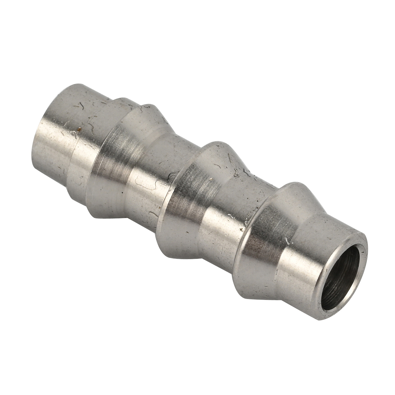
Micro-burrs disproportionately impact small-scale manufacturing operations. A fraction of a millimeter of displaced material easily causes catastrophic assembly failures. It blocks fluidic pathways in medical devices and contaminates sterile systems. Burr formation on CNC machined parts drives up compounding production issues across the shop floor. You face high scrap rates, compromised dimensional tolerances, and delayed shipping schedules. Manual deburring under magnification carries unsustainable labor requirements and introduces severe human error. We must shift focus from reactive post-processing to proactive, in-process burr mitigation. True precision requires controlling part design, cutting mechanics, material behavior, and supplier capabilities. Relying on secondary operations to fix poor machining practices destroys profit margins and degrades overall part quality.
In-process burr mitigation through optimized toolpaths, high-pressure coolant, and precise cutting parameters is vastly more cost-effective than secondary deburring operations.
Design for Manufacturability (DFM) is the first line of defense; engineering out sharp intersections prevents internal burrs before production begins.
Material selection and grain structure dictate burr behavior; understanding machinability ratings is critical for custom machined metal parts.
Swiss-type machining offers distinct advantages over conventional turning for minimizing tool deflection and burr size in miniature components.
Partnering with a specialized precision CNC machining supplier equipped with high-resolution metrology is mandatory for validating burr-free micro-components.
The Mechanics of Burr Formation in Miniature Components
Establishing the baseline for acceptable edge breaks dictates your entire manufacturing approach. You must differentiate between a functional edge transition and a critical defect. Micro-manufacturing demands strict adherence to edge condition tolerances. Even microscopic material displacement alters the fundamental geometry of small components, leading to immediate rejection during quality control inspections.
Classifying Burr Types in Micro-Machining
Machining forces displace material in predictable patterns based on tool geometry and cutting direction. Understanding these patterns dictates your mitigation strategy at the spindle. We classify these defects into three primary categories based on their formation mechanics.
Poisson Burrs: These form through lateral deformation. Compressive forces push material outward perpendicular to the cutting direction. They often appear on the top edges of milled slots where the material yields sideways rather than shearing cleanly.
Roll-Over Burrs: These are exit burrs. The tool pushes material over the edge instead of shearing it. They occur when the material yields plastically at the end of a cut, bending over the edge like a hinge.
Breakout Burrs: These result from brittle fracture. The material snaps off before the cutting edge completes the shear zone. This leaves a jagged, irregular edge on the workpiece, common in cast iron or heavily hardened steels.
Why Micro-Scale Amplifies Burr Impact
The ratio of burr size to part size dictates the severity of the defect. A 0.05mm burr on a large engine block casting is negligible. That same burr on precision machined miniature components changes the geometry significantly. This dimensional shift causes immediate functional failure in tight-tolerance assemblies.
Functional risks multiply rapidly in micro-applications. A micro-burr disrupts fluid flow in medical delivery devices, causing incorrect dosing. It causes electrical shorts in high-density aerospace connectors by bridging contact pins. It generates unacceptable friction in micro-gear assemblies, leading to premature wear and motor burnout. Removing these defects without altering the core geometry requires extreme precision and specialized equipment.
Design for Manufacturability (DFM): Engineering Out Burrs
Mechanical engineers control burr formation during the initial CAD phase. Upstream mitigation naturally resists burr formation during the machining process. Smart design choices eliminate the physical conditions that cause material to tear or roll, saving countless hours of troubleshooting on the shop floor.
Managing Intersecting Holes and Complex Geometries
Internal burrs pose the highest risk in manufacturing because they are hidden from visual inspection. Cross-holes in manifolds and fluidic devices are notorious for trapping burrs. The tool exit at the intersection pushes material into the adjacent cavity. Reaching these internal burrs for removal is notoriously difficult and often requires specialized tooling.
Implement specific DFM solutions to manage these intersections effectively.
Alter intersection angles to approach exactly 90 degrees. Acute angles create thin, weak edges that roll easily under cutting pressure.
Step hole diameters so the smaller hole intersects the larger one. This allows the larger tool to clean up the burr left by the smaller drill.
Design relief cuts at the intersection to allow clean tool exits.
Avoid placing critical sealing surfaces directly adjacent to cross-hole intersections.
Standardizing Edge Break Callouts on CAD Models
Ambiguous drawing notes create severe manufacturing conflicts. Notes like "remove all sharp edges" leave the edge condition entirely open to interpretation by the machinist. This subjective standard guarantees inconsistent results across different production batches and different operators.
Advocate for specific, quantifiable callouts on all engineering drawings. Specify exact chamfer dimensions or maximum allowable radii. Utilize ISO 13715 standards to define edge states mathematically. Clear geometric dimensioning aligns your expectations directly with your precision CNC machining supplier. This eliminates guesswork, standardizes quality control, and prevents costly rework.
Proactive Strategies to Minimize Burrs on CNC Machined Parts
Engineering controls applied at the machine level prevent burrs before they form. Controlling the cutting environment requires precise synchronization of tools, speeds, and coolants. We must manage the shear zone to ensure clean material separation rather than plastic deformation.
Optimizing Cutting Parameters (Speeds and Feeds)
The relationship between feed rate, spindle speed, and chip thickness dictates edge quality. High feed rates increase chip thickness and cutting forces. This heavily exacerbates plastic deformation and creates large roll-over burrs at the tool exit. Conversely, low feed rates cause the tool to rub rather than cut.
Avoid this rubbing effect at all costs. Rubbing generates excessive heat and work-hardens the material surface, making subsequent passes even more difficult. Maintain a sharp cutting edge and calculate feeds to ensure consistent chip loads. Proper parameter optimization keeps the material in the shear zone, preventing lateral displacement and minimizing edge tearing.
Tool Selection and Geometry
Tool geometry directly impacts shearing efficiency. Positive rake angles lift the chip cleanly away from the workpiece, reducing cutting pressure. High helix angles evacuate chips rapidly, preventing recutting. Edge preparation must match the material's specific shear characteristics; a dead-sharp edge works for aluminum, while a slight hone is necessary for hardened steels.
Micro-grain carbide tools provide the sharpest possible cutting edges for miniature work. Specialized coatings like TiAlN maintain this sharpness during extended production runs. The coating reduces friction and thermal transfer into the tool substrate. A sharp, coated tool cuts cleanly through the exit, minimizing roll-over burrs and extending tool life.
Advanced Toolpath Strategies
Toolpath direction heavily influences where and how the burr forms. Climb milling pushes the burr into the thickest part of the chip, shearing it off cleanly. Conventional milling pulls the burr outward, leaving it attached to the workpiece. Climb milling is vastly superior for clean edge exits on external profiles.
Implement in-process chamfering and radiusing within the CNC program. Program strategic tool exit vectors to roll any unavoidable burrs into non-critical areas. Ramping out of a cut gradually reduces chip thickness. This gradual exit prevents the sudden material yielding that causes heavy burrs, leaving a much cleaner edge transition.
High-Pressure Coolant and Chip Evacuation Systems
Chip recutting is a major cause of secondary burrs and poor surface finishes. High-pressure, through-tool coolant blasts chips out of the cutting zone immediately. Operating at 1,000 PSI or higher prevents the tool from crushing old chips against the freshly cut edge.
Coolant lubricity plays a vital role in edge preservation. High-lubricity fluids reduce friction at the tool-workpiece interface. This lowers cutting temperatures and minimizes plastic deformation. Keeping the material cool prevents the ductile yielding that leads to severe roll-over burrs, especially in gummy materials like stainless steel.
Material Considerations for Custom Machined Metal Parts
Raw material properties directly influence the severity and type of burr generated. You must evaluate materials based on their specific machining characteristics. The metallurgical structure dictates how the material separates under cutting pressure, which directly impacts your custom machined metal parts.
Machinability Ratings and Burr Tendencies
Ductile materials stretch and deform before they shear. Alloys like 316L Stainless Steel and pure Copper are highly prone to large roll-over burrs. They require exceptionally sharp tools, aggressive rake angles, and high-lubricity coolant to cut cleanly without tearing.
Brittle materials fracture easily under cutting forces. Materials like Brass and Cast Iron tend to form breakout burrs. Alloying elements alter these behaviors significantly. Adding lead or sulfur creates free-machining steels. These elements break up the chips and drastically reduce burr formation, allowing for faster feed rates and longer tool life.
Heat Treatment and Grain Structure Impacts
Pre-hardening materials alters their ductility and machinability. Hardening steel reduces its tendency to stretch and roll over the edge. Machining materials in a pre-hardened state, such as 17-4 PH in the H900 condition, often results in significantly smaller burrs compared to machining them in an annealed state.
Evaluate the mechanical trade-offs carefully. Machining hardened materials increases tool wear and requires more rigid setups. However, post-machining heat treatment introduces severe distortion risks for miniature components. Balancing tool life against edge quality is a critical engineering decision that impacts the entire production run.
Specialized Equipment: Swiss CNC Machined Parts vs. Conventional Turning
Assessing the right machinery is critical for high-volume, burr-sensitive production. The physical architecture of the machine dictates its ability to hold tight tolerances. Equipment rigidity directly correlates to edge quality and burr reduction.
Advantages of Swiss-Type Lathes for Micro CNC Machined Precision Parts
Swiss-type lathes utilize a guide bushing to support the raw material. The cutting tool engages the material mere millimeters from this support. This mechanical arrangement eliminates material deflection during the cutting process, regardless of the part's length.
This extreme rigidity translates to exceptionally clean cuts. It significantly reduces burr formation on high-length-to-diameter ratio parts. Producing micro CNC machined precision parts requires this level of stability. Swiss CNC machined parts consistently exhibit superior edge conditions compared to traditional turning methods, often eliminating the need for secondary deburring entirely.
Evaluating Custom CNC Turning Parts for Burr-Free Finishes
Conventional chucking lathes have distinct limitations for miniature components. Holding a small diameter part in a main spindle chuck allows the unsupported end to deflect under cutting pressure. Deflection causes chatter, poor surface finishes, and heavy burr formation at the tool exit.
Conventional turning remains acceptable for larger, more rigid components. When producing custom CNC turning parts, utilize live tooling for in-machine deburring. Program cross-drilling and milling operations to include automated edge breaks. This keeps the part in the machine, maintains datum references, and eliminates secondary handling.
Post-Process Deburring vs. In-Process Mitigation
You must evaluate the qualitative comparison between preventing burrs and removing them. Relying on secondary operations introduces variables that threaten part geometry. In-process mitigation always provides superior dimensional control and consistency.
The Hidden Costs of Manual Deburring
Manual deburring under microscopes is a high-risk operation. It introduces human inconsistency into a precision manufacturing environment. Operators use scalpels, abrasive files, and rotary tools to remove microscopic defects by hand.
This process carries immense labor requirements. It also risks dimension alteration on critical features. A slight slip of a hand tool ruins a tight tolerance immediately, turning a good part into scrap. Manual deburring is not a scalable or reliable solution for micro-manufacturing.
Automated and Secondary Deburring Technologies
Mass-finishing options exist for bulk deburring. Centrifugal barrel tumbling uses abrasive media and high G-forces to wear down edges. Electrochemical machining (ECM) dissolves burrs using targeted electrical currents. The thermal energy method (TEM) burns off burrs using a combustible gas mixture.
Deburring Technology
Mechanism of Action
Best Application
Primary Risk
Centrifugal Tumbling
Abrasive media friction
External edges on rigid parts
Media lodgment in micro-holes
Electrochemical (ECM)
Anodic dissolution
Internal cross-holes
Stray etching on critical surfaces
Thermal Energy (TEM)
High-heat combustion
Complex internal manifolds
Metallurgical changes from heat
Cryogenic Deflashing
Freezing and media blasting
Plastics and soft metals
Surface finish degradation
Advanced methods suit precision components better. Cryogenic deburring freezes parts to embrittle the burrs, then blasts them with polycarbonate media. Micro-abrasive blasting targets specific areas with fine particulate streams. However, all secondary operations carry risks. Media lodgment, edge rounding beyond tolerance, and surface finish degradation remain constant threats to part quality.
Evaluating a Precision CNC Machining Supplier for Burr Control
Vetting a manufacturing partner ensures they can deliver on strict edge-condition requirements. You must audit their equipment, processes, and quality control systems. A supplier's approach to burr management reveals their overall technical competence and commitment to precision.
Quality Control and Metrology Capabilities
Visual inspection with the naked eye is insufficient for micro-components. Specify the exact inspection equipment required to verify micro-burr removal. Suppliers must utilize optical comparators, scanning electron microscopes (SEM), and tactile coordinate measuring machines (CMM) to validate edge conditions.
Define "burr-free" with quantifiable metrics in your drawing notes. Specify maximum allowable edge protrusions in microns. Verify these metrics during inspection using high-resolution metrology. If a supplier lacks this equipment, they cannot guarantee micro-precision or repeatable quality.
Process Validation and Scrap Mitigation
Procurement teams must interrogate a supplier's validation processes. Ask specific questions regarding their First Article Inspection (FAI) protocols. Request data on their statistical process control (SPC) implementations for critical edge dimensions.
Evaluate the supplier's standard operating procedures for tool life management. Tools wear down, and dull tools create burrs. The supplier must have strict tool replacement schedules to prevent burr spikes. Proactive tool management, rather than running inserts until they fail, is the foundation of scrap mitigation.
Conclusion
Update all CAD drawings to replace ambiguous "remove sharp edges" notes with specific ISO 13715 edge break callouts.
Implement DFM reviews to alter intersecting cross-holes, ensuring angles approach 90 degrees to minimize internal burr formation.
Audit your current manufacturing partners to verify they possess Swiss-type lathes and high-resolution metrology equipment.
Require suppliers to submit documented tool life management procedures and SPC data for all critical micro-components.
Transition away from manual deburring by programming in-process chamfers and utilizing live tooling on your CNC equipment.
FAQ
Q: What is the maximum acceptable burr size on micro CNC machined precision parts?
A: Acceptable burr size depends entirely on application-specific tolerances. Utilizing ISO 13715 standards allows you to define exact limits on your engineering drawings. For micro-components, maximum allowable edge deviations are typically restricted to under 0.01mm. Exceeding this limit often causes mechanical interference, fluidic blockages, or complete functional failure in miniature assemblies.
Q: How does climb milling reduce burr formation compared to conventional milling?
A: Climb milling starts with maximum chip thickness and tapers to zero at the exit. This pushes the cutting forces into the workpiece, shearing the material cleanly. Conventional milling starts at zero and increases, pulling material outward at the exit, which actively promotes plastic deformation and roll-over burr formation.
Q: Can Swiss machining eliminate the need for deburring entirely?
A: Yes, in many cases. The extreme rigidity of the guide bushing eliminates material deflection. Combined with sharp tooling, high-pressure coolant, and in-process programmed edge breaks, Swiss machining often produces parts that require zero secondary deburring operations, saving significant time and labor.
Q: What is the best material for custom machined metal parts to avoid burrs?
A: Free-machining alloys are the best choice for burr prevention. Brass 360 and Aluminum 2011 contain specific alloying elements that cause chips to fracture cleanly. This brittle chip formation prevents the plastic deformation that causes roll-over burrs, allowing for faster machining speeds and cleaner edges.
Q: How do you inspect for burrs on precision machined miniature components?
A: Inspection requires high-resolution metrology equipment. Optical microscopy and automated vision systems verify external edge conditions. Tactile probing and scanning electron microscopes (SEM) are used to detect internal burrs and measure microscopic edge deviations accurately, ensuring compliance with strict engineering tolerances.
Q: What is the difference between a roll-over burr and a breakout burr?
A: A roll-over burr occurs through plastic deformation when a tool pushes ductile material over an edge, bending it like a hinge. A breakout burr occurs through brittle fracture when the material snaps off before the tool completes the cut, leaving a jagged, irregular edge.
Q: Why is manual deburring not recommended for custom CNC turning parts under 5mm?
A: Manual deburring introduces severe human error and inconsistency. On parts under 5mm, hand tools easily alter critical micro-tolerances, turning good parts into scrap. Additionally, the labor costs associated with deburring under a microscope make it financially unsustainable for high-volume production runs.