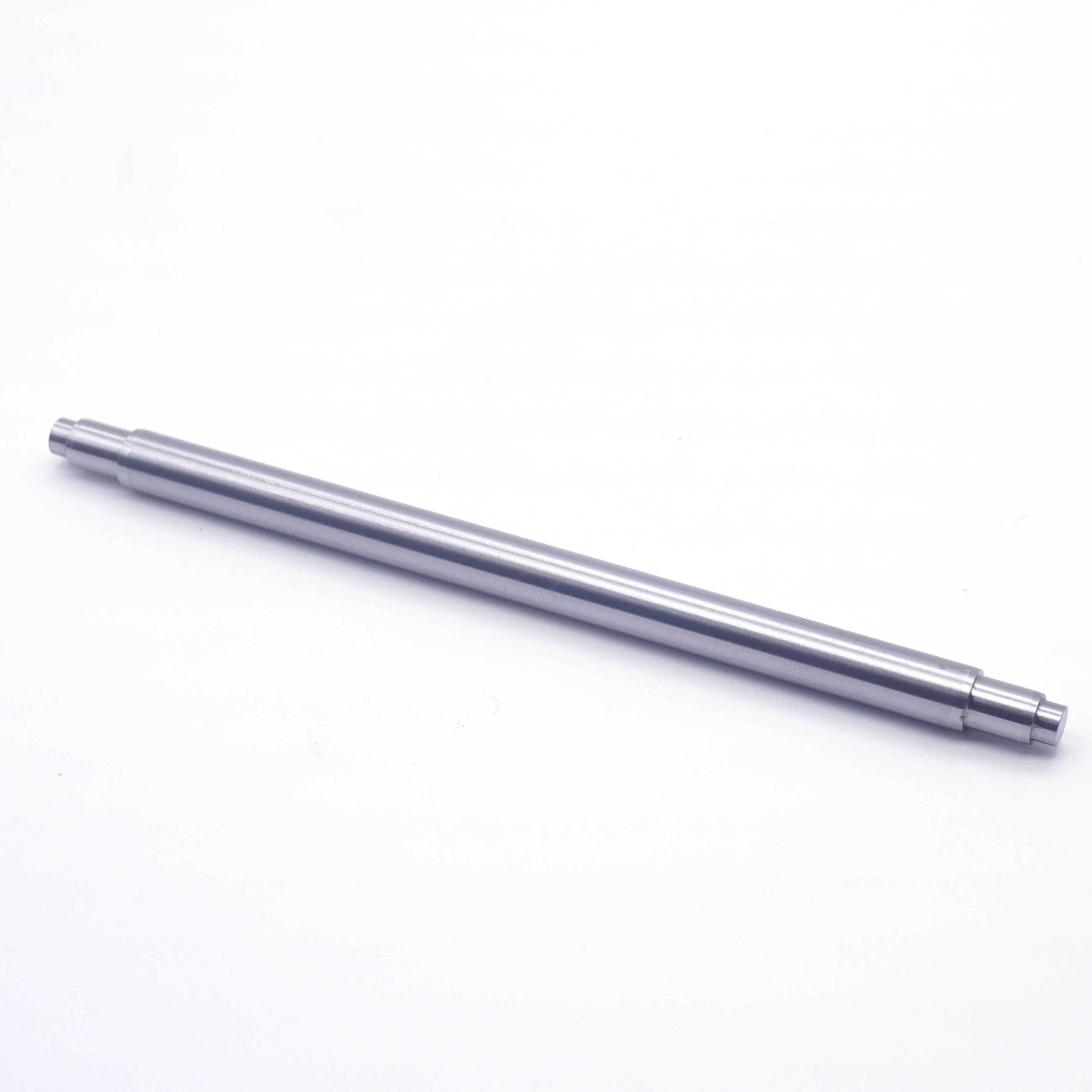
Frame pin selection acts as a critical structural decision in mechanical design. Specifying the wrong fastener compromises assembly integrity, alignment, and operational safety. We are dealing with high-tolerance metal industrial positioning pins used in mechanical engineering, not the wooden dowels used in carpentry and furniture making. The stakes in industrial applications are significantly higher.
Misapplication carries severe engineering and financial costs. Using a rigid alignment pin in a dynamic pivot point causes premature wear and catastrophic binding. Conversely, deploying a loose linkage pin for structural alignment results in unacceptable tolerance stack-up and eventual assembly failure. You cannot interchange these components without risking the entire mechanical system.
To definitively choose between these two fastener types, you must evaluate specific operational parameters. This requires a deep understanding of load profiles, fit tolerances, and retention mechanisms to definitively choose between a dowel pin and a clevis pin for specific industrial applications.
Functional Divergence: A dowel pin is engineered for static, high-precision alignment and shear load transfer, whereas a clevis pin is designed to allow rotational movement in dynamic pivot points.
Tolerance Requirements: Precision dowel pins require exact interference (press) or slip fits, demanding tighter machining tolerances than the clearance fits typical of clevis pins.
Retention Mechanisms: Clevis pins rely on secondary fasteners (cotter pins, clips) for lateral retention, while dowel pins typically rely on friction, adhesives, or blind hole seating.
Sourcing Strategy: Selecting the right shaft pin manufacturer depends on the need for standard off-the-shelf components versus custom CNC machined dowel pins tailored for unique environmental or load conditions.
Defining the Core Mechanics: Dowel Pins vs. Clevis Pins
What is a Dowel Pin?
A dowel pin is a solid, cylindrical fastener utilized primarily to align machine components before final bolting. These components function as highly accurate industrial positioning pins. They ensure mating parts sit in the exact required orientation. They share a symbiotic relationship with threaded fasteners in mechanical design. The pins handle transverse shear forces and precise alignment. Meanwhile, bolts and screw sockets manage the tensile clamping forces.
Standard geometries for these fasteners include chamfered ends or radiused ends. This design facilitates easier insertion into precisely machined holes. Notably, they lack integrated locking features like heads or cross-holes. Their effectiveness relies entirely on precise dimensional accuracy. Manufacturers often use centerless grinding to bring them to exceptionally tight tolerances to guarantee a proper fit. When you press one into a reamed hole, the friction alone holds the assembly together.
What is a Clevis Pin?
A clevis pin is a headed, cylindrical fastener integrated into a clevis fastener assembly. It creates a secure but flexible mechanical linkage. Unlike rigid alignment pins, this component allows connected parts to pivot freely along its central axis. This rotational freedom is essential for linkages requiring articulation, such as hydraulic cylinder rods or steering tie rods.
The standard geometry features a distinct head on one end. The opposite end typically contains a cross-hole or a machined groove. This design accommodates secondary retention hardware. In an industrial clevis pin application, the component passes through the prongs of a clevis yoke and the eye of a mating rod. This forms a robust hinge capable of sustaining significant operational loads while moving.
Primary Application and Success Criteria
Static Alignment vs. Dynamic Pivoting
Success criteria for static alignment demand zero relative movement between joined components. The assembly must support repeatable disassembly and reassembly without any loss of positional accuracy. Think of an engine block and a cylinder head. You need them to line up perfectly every single time before you torque the head bolts down. This strict requirement falls squarely into the territory of alignment pins. They lock parts rigidly in place.
Conversely, success criteria for dynamic pivoting focus on movement. The joint requires low-friction rotation and high resistance to binding under heavy loads. Engineers also prioritize the ease of visual inspection for wear and retention integrity. If a linkage seizes up because the pin tolerance was too tight, the entire machine stops. These operational demands dictate the use of clevis linkages.
Load Bearing and Shear Strength Considerations
A precision dowel pin handles pure shear forces across the mating plane of two rigid components. The load acts perpendicular to the pin's longitudinal axis. Because the components sit flush against each other, the pin experiences single or double shear without significant bending moments. This requires high material hardness and exact hole sizing to prevent deformation.
A clevis linkage handles both bending moments and shear forces within a multi-part assembly. Applications like hydraulic cylinder mounts and turnbuckles subject the pin to varying load directions. The gap between the clevis prongs and the mating rod eye introduces bending stress. Calculating the required pin diameter involves analyzing anticipated operational loads against the material's yield strength.
Mechanical Feature
Dowel Pins
Clevis Pins
Primary Function
Static alignment and positioning
Dynamic pivoting and linkage
Load Handling Profile
Pure shear forces (single/double)
Shear forces and bending moments
Required Fitment
Interference (press) or slip fit
Clearance fit for free rotation
Retention Strategy
Friction, adhesives, blind seating
Cotter pins, retaining rings, clips
Physical Geometry
Straight cylinder, chamfered ends
Headed cylinder, cross-hole/groove
Contextualizing Alternatives: When to Spec Other Pin Types
Mechanical design offers several alternative fasteners, each suited to specific conditions. Spring pins, often called roll pins, differ significantly from solid alignment pins. While solid pins provide rigid shear strength, spring pins compress during installation. They absorb vibration and accommodate wider hole tolerances in lower-precision assemblies. You drive them in with a hammer, and their outward spring tension holds them in place.
Taper pins serve a different primary function. Engineers prefer taper pins for torque transmission in rotating shafts. Their wedging action secures hubs to shafts effectively. You ream a tapered hole, drive the pin in, and the friction locks the hub. However, solid cylindrical pins remain the superior choice for flat-plane alignment between stationary plates.
Hitch pins share visual similarities with clevis linkages but serve different operational needs. Hitch pins facilitate rapid, tool-less coupling and uncoupling in towing and agricultural applications. They utilize handles or rings for manual extraction. Clevis linkages remain permanent or semi-permanent, secured firmly with cotter pins or retaining clips.
Technical Evaluation Dimensions
Tolerance, Fit Types, and Standard Designations
Engineering fits define the functional success of these fasteners. Alignment pins require specific interference (press) fits for the holding component. The mating component typically utilizes a transition or slip fit. This precise sizing ensures the pin remains firmly anchored in one side while allowing the other side to assemble without galling. If you drill a 0.250-inch hole, you might specify a pin that is 0.2502 inches for a tight press fit.
Clevis linkages require clearance fits. The pin must rotate freely without excessive radial play. Tight tolerances here would cause binding under load or thermal expansion. Loose tolerances would accelerate wear and induce shock loading during directional changes. You generally want a few thousandths of an inch of clearance to allow for grease penetration and thermal expansion.
Standard specifications govern manufacturing dimensions. ASME B18.8.2 outlines strict requirements for unhardened and hardened ground pins. Tolerance classes directly impact manufacturing costs. Tighter tolerances require secondary grinding operations. You must consult standard designation tables for nominal diameters and lengths before specifying custom sizes to control project budgets.
Fastening and Retention Methods
Friction serves as the primary retention method for alignment pins. The interference fit generates sufficient radial force to hold the component in place. When installing these into blind holes, trapped air can cause hydraulic lock. If you press a standard pin into a blind hole filled with grease or trapped air, it will push back out. Engineers specify pins with air release flats or spiral grooves to vent this pressure during insertion.
Secondary retention is mandatory for pivoting linkages. Traditional designs utilize a cross-hole to accept a cotter pin or safety wire. Alternatively, a grooved clevis pin accommodates retaining rings or E-clips. This grooved design offers a lower profile and eliminates the sharp edges associated with bent cotter pins. It also speeds up assembly on the factory floor.
Material Selection and Environmental Resistance
Material selection dictates load capacity and longevity. Hardened alloy steel, like 4140, provides maximum shear strength for alignment applications. The hardening process prevents deformation under extreme transverse loads. However, alloy steel offers limited corrosion resistance without secondary treatments. If left bare in a humid environment, it will rust and seize in the hole.
Pivoting linkages frequently operate in outdoor or corrosive environments. Manufacturers highly utilize 300 and 400 series stainless steel for these components. Stainless steel sacrifices some ultimate shear strength for superior environmental resistance. Surface treatments like zinc plating, passivation, or black oxide further enhance durability. You must account for the dimensional thickness of these platings when calculating final fit tolerances. A 0.0005-inch zinc plating adds 0.001 inches to the overall diameter.
Customization and Manufacturing Trade-Offs
When to Spec Custom CNC Machined Dowel Pins
Standard catalog components cover most engineering requirements. However, specific scenarios demand custom CNC machined dowel pins. Applications may require non-standard diameters to match legacy equipment. You might need stepped profiles to act as positive stops within an assembly. Extreme environments might necessitate specific Rockwell hardness levels or proprietary superalloys like Inconel or Monel.
You must carefully weigh the cost-to-benefit ratio of custom machining. Custom components incur setup fees and longer lead times. Whenever possible, alter assembly designs to accommodate standard off-the-shelf pins. Specify custom machining only when standard options compromise structural integrity or operational performance.
Evaluating a Shaft Pin Manufacturer
Selecting a reliable shaft pin manufacturer mitigates supply chain and quality risks. Vet potential suppliers against stringent criteria. Look for active ISO 9001 certifications. Verify their in-house centerless grinding capabilities, which are essential for holding tight diametrical tolerances.
Demand comprehensive quality control documentation. A qualified manufacturer provides lot traceability, material certifications, and Production Part Approval Process (PPAP) documentation. Assess their capability to scale production. A supplier must transition smoothly from low-volume prototyping to high-volume production without experiencing tolerance drift or quality degradation.
Implementation Risks and Mitigation Strategies
Galling, Binding, and Wear in Pivot Joints
Pivot joints face significant mechanical risks. Unlubricated or improperly toleranced pins can gall against mating yokes. Galling involves the microscopic transfer of material between sliding surfaces, leading to rapid joint failure and seizure. Once a pin galls, you usually have to cut it out with a torch or a grinder.
Mitigate this risk by specifying appropriate clearance tolerances. Select dissimilar metals for the pin and the clevis to reduce adhesive wear. Incorporate lubrication pathways, such as grease zerks and internal cross-drilling. Utilize bronze or polymer bushings within the mating rod eye to isolate wear and simplify maintenance. When the bushing wears out, you replace it instead of replacing the entire steel yoke.
Over-Constraining Assemblies with Precision Dowel Pins
Engineers often over-constrain assemblies by using too many alignment pins. Inserting three or more tight-fitting pins into a single mating plane leads to severe tolerance stack-up. The parts will bind during assembly. Forcing them together induces internal component stress and warps the assembly.
Apply the 3-2-1 principle of location to mitigate this risk. Use one standard round pin for primary location. Use a second diamond (relieved) pin to control rotation. The diamond pin accommodates center-distance variations between the machined holes. This strategy ensures precise alignment without over-constraining the physical parts. Never use more than two alignment pins on a single mating surface.
Conclusion
Dowel pins remain the definitive choice for rigid, high-precision alignment and heavy shear loading. They lock components securely in static configurations. Conversely, clevis pins are essential for secure, pivoting mechanical linkages where dynamic movement is required. Understanding these functional boundaries prevents catastrophic assembly failures.
Follow these next steps to finalize your mechanical fastener specifications:
Review your current CAD models to identify potential tolerance stack-up issues across all mating surfaces.
Consult material specification sheets to match pin hardness and yield strength with anticipated operational shear loads.
Calculate the exact clearance or interference fit required based on thermal expansion coefficients of your chosen metals.
Request prototype samples from a qualified manufacturer to conduct physical fitment and load testing.
Update your assembly documentation to specify the exact installation method, including required press force or lubrication procedures.
FAQ
Q: Can a dowel pin be used as a pivot pin?
A: Generally, no. They lack retention features like heads or cross-holes, risking lateral migration under vibration. Their tight tolerances also cause binding during rotation. If you must use one for pivoting, you have to design custom retaining rings and specify looser clearance fits to prevent the joint from seizing.
Q: What are the differences between a hitch pin and an industrial clevis pin?
A: Both connect mechanical linkages, but their applications differ. Hitch pins feature a handle or ring for quick, frequent manual removal in towing or agriculture. Clevis linkages are typically semi-permanent. They sit flush and are secured tightly with cotter pins or retaining clips in industrial machinery.
Q: What is the standard tolerance for a precision dowel pin?
A: Standard tolerances depend on the specific engineering requirement. Precision applications typically use oversize or undersize tolerances ranging from +/- 0.0001 to 0.0002 inches. This exact sizing allows engineers to achieve perfect press fits or slip fits without compromising the holding force.
Q: How do you remove a dowel pin from a blind hole?
A: Extracting pins from blind holes requires specific techniques. You can use internally threaded pins and extract them with a slide hammer. Alternatively, hydraulic pressure can force the pin out if a fluid pathway exists. Specialized collet puller tools also grip the exposed pin diameter for extraction.
Q: What is the advantage of a grooved clevis pin over a standard cross-hole clevis pin?
A: Grooves allow the installation of snap rings or E-clips. This provides a significantly lower profile than a bent cotter pin. It eliminates sharp wire ends that can snag on equipment or personnel. Grooved designs also support faster automated or manual assembly on production lines.
Q: Can spring pins be used instead of precision dowel pins for alignment?
A: Spring pins absorb vibration and reduce manufacturing costs because they accommodate looser hole tolerances. However, they lack the solid rigidity and exact dimensional accuracy required for high-precision alignment. They compress under load, making them unsuitable for strict tolerance assemblies.
Q: How do I calculate the required shear strength for an industrial positioning pin?
A: Calculate shear strength by multiplying the pin's cross-sectional area by the material's ultimate shear strength. Determine if the application places the pin in single or double shear. Always apply an appropriate safety factor to account for shock loading, fatigue, and environmental degradation over time.