When two suppliers describe the same component as a CNC turned part and a CNC lathed part, the wording can make the quotations seem based on different manufacturing processes. In practice, both terms usually refer to machining a rotating workpiece with cutting tools to create round or rotationally symmetrical features.
The real choice lies in the machine setup, feature geometry, tolerance relationships, batch size, and need for secondary operations. Understanding these factors helps engineers and buyers decide whether CNC turning parts require basic two-axis machining, live tooling, or a combined turn-mill process.
Turning and Lathing: Different Words, Same Cutting Principle
Why Both Terms Appear in Drawings and Quotations
“Turning” usually names the machining operation, while “lathe” names the machine that performs it. “Lathing” is a less formal expression that some suppliers use in quotations, catalogs, and product classifications. Other common descriptions include CNC lathe machining, precision lathe parts, CNC turned components, and custom turning services.
These terms do not automatically indicate different levels of precision or different cutting methods. Regional language, internal product organization, customer vocabulary, and marketing preferences often explain why one manufacturer favors “turning” while another uses “lathing.” At HANYEE, both categories cover computer-controlled machining for custom shafts, pins, bushings, and similar components.
Consequently, buyers should not decide between quotations based on terminology alone. One supplier may use “CNC lathing” for straightforward two-axis work, while another may use the same phrase for a turning center equipped with powered tools and additional axes. The process label is only the starting point; the planned operations reveal whether the route fits the part.
What the Process Can Produce
In both CNC turning and CNC lathing, bar stock, tubing, or a prepared blank is secured in a chuck or collet. As the material rotates around its centerline, tools remove material from external and internal surfaces. This motion naturally supports cylindrical, conical, stepped, grooved, bored, and threaded geometries.
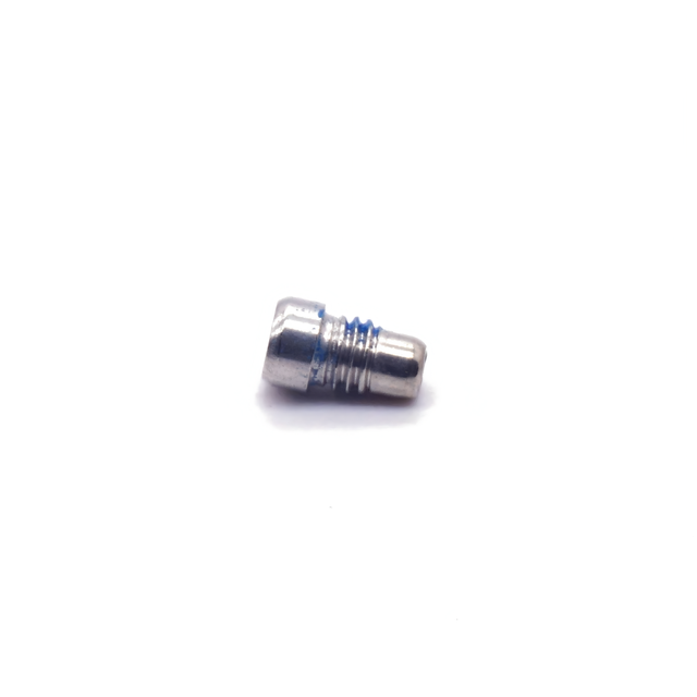
Typical CNC turning parts include shafts, pins, bushings, sleeves, spacers, collars, rods, and threaded fittings. HANYEE applies this capability to pins, bushings, rods, and other products whose main features follow rotational symmetry.
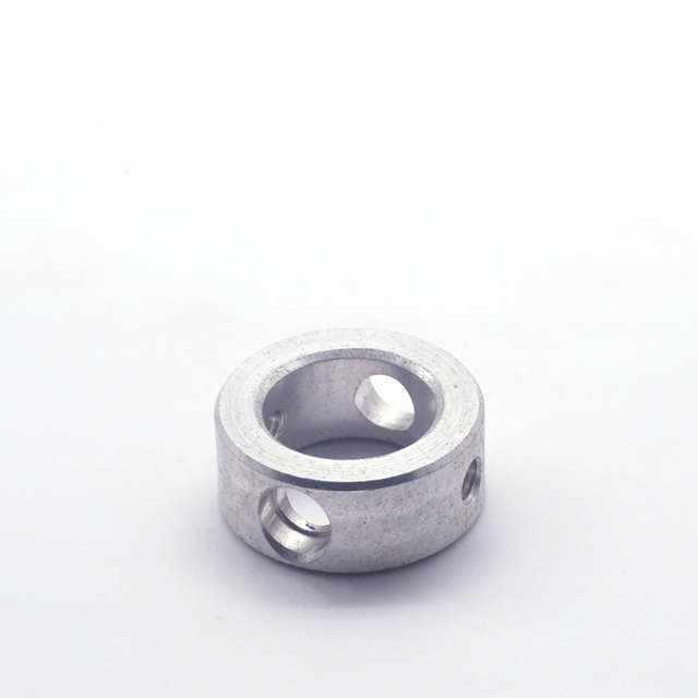
Part names alone, however, do not determine the complete route. A shaft with only stepped diameters may stay on a basic lathe, whereas a shaft collar with side holes introduces off-axis work. Two components can both be called turned parts while requiring substantially different machines, tooling, workholding, and inspection plans.
The Machine Setup Changes More Than the Name
Where Basic Two-Axis Turning Works Well
A conventional CNC lathe primarily controls tool movement along the X and Z axes. The X axis governs radial movement toward or away from the spindle centerline, while the Z axis controls movement along the workpiece length. This arrangement is well suited to parts whose important features follow one axis of rotation.
Common two-axis operations include facing, straight turning, taper turning, boring, grooving, threading, chamfering, and parting. A bushing with controlled inside and outside diameters, for example, can often be completed efficiently without powered milling tools. The same applies to uncomplicated pins, sleeves, threaded studs, and spacers whose features remain concentric or axial.
Basic equipment can offer practical cost advantages for such CNC turning parts. Programming is usually more direct, tooling requirements are easier to manage, and setup may involve fewer variables. Paying for additional axes does not improve a part that contains no side features or complex positional relationships.
When Live Tooling or Additional Axes Matter
A turning center can extend beyond standard X-Z motion by adding C-axis spindle positioning, Y-axis movement, live tooling, a sub-spindle, or automated bar feeding. The C axis positions or rotates the workpiece for controlled face and lateral machining, while powered tools can drill, tap, or mill without transferring the component to a separate machine. Multi-axis turn-mill configurations may also use a sub-spindle to machine the opposite end of the stock.
These capabilities become relevant when drawings include flats, cross-holes, side slots, radial threads, keyways, off-center holes, or back-side details. A collar with a side hole may be turned and drilled in one clamping, helping preserve the relationship between the bore and the hole position. Likewise, a sub-spindle may reduce manual handling when both ends of a component require controlled features.
More capability is not automatically more economical. Advanced machines require appropriate programming, driven-tool holders, setup knowledge, and process validation. For a simple spacer, using a multitasking center may add cost without creating meaningful quality or lead-time benefits.
Table: What to Confirm Behind Each Process Description
Description in the Quote
Likely Meaning
What the Buyer Should Ask
CNC turning
General machining of a rotating workpiece
How many axes and setups are planned?
CNC lathing
Usually another term for CNC turning
Is the proposed route basic or multi-axis turning?
Live-tool turning
Turning with powered drilling or milling tools
Which off-axis features remain in one setup?
Turn-mill machining
Turning and milling within one coordinated route
Will all critical features share the same clamping?
Secondary milling
The turned component moves to another machine
How will datums and positional tolerances be transferred?
Let the Part Drawing Decide the Machining Route
Begin With the Part’s Dominant Geometry
The drawing should first be assessed for its dominant geometry. When most of the component is cylindrical, tubular, conical, or arranged around a shared centerline, turning is generally the logical primary process. Outside diameters, bores, shoulders, grooves, tapers, and axial threads can all be generated naturally as the workpiece rotates.
Shafts, pins, bushings, and spacers are common examples, but the decision should not rely only on the product name. A fitting may be mostly rotational and therefore ideal for turning, while another fitting may contain several flat faces and intersecting passages that make milling equally important. HANYEE produces assembly components, brass spacers, shoulder screws, shaft collars, and other custom parts with varying feature complexity.
Parts dominated by broad planar surfaces, deep pockets, extensive bolt patterns, or freeform contours may need milling as the primary route. Turning can still create a bore, thread, or round interface, but it should not be forced to lead a process when most material removal occurs away from the rotational axis. The objective is to assign each feature to the method that can produce it most efficiently and consistently.
Count Features That Sit Away From the Centerline
Off-axis features often determine whether standard turning is sufficient. Cross-drilled holes, milled flats, radial threads, side slots, eccentric details, bolt patterns, and back-side machining all require additional access. Their number, complexity, and relationship to the turned surfaces should be reviewed before approving a route.
Three production strategies are common:
1. Complete the rotational features on a basic lathe, then transfer the part for secondary milling or drilling.
2. Use live-tool turning to machine a limited number of off-axis details during the same clamping.
3. Divide the work between turning and milling when separate operations provide a better balance of flexibility, cycle time, and tooling cost.
A transfer between machines is not inherently poor practice. For a prototype or small batch with a simple cross-hole, secondary drilling may cost less than preparing a multitasking program and specialized tooling. When that hole has a tight positional relationship to a bearing diameter, however, completing both features in one setup may reduce datum-transfer risk.
The volume of off-axis work also matters. One milled flat on an otherwise cylindrical part still supports a turning-led route. A component with several deep pockets, angled surfaces, and complex multi-face features may be better treated as a milled part with selected turned details.
Protect the Dimensions That Control Assembly
Functional relationships deserve more attention than isolated tolerance values. Bore-to-outer-diameter concentricity, shoulder perpendicularity, bearing-seat runout, thread alignment, and hole position relative to a turned diameter can directly affect assembly performance. These requirements help determine which features should share a setup and datum structure.
Removing a component from one fixture and clamping it again requires the next operation to re-establish its location. Even with capable equipment, the second setup introduces workholding, alignment, and datum-transfer variables. A single clamping can therefore be valuable when a cross-hole must align closely with a bore, several diameters share a common axis, or front and rear features must maintain a controlled relationship.
This principle is relevant to HANYEE’s custom precision assembly components. The manufacturing decision should be based on how the part locates, fastens, rotates, or mates within the assembly—not on whether it is described commercially as turned or lathed.
Engineers can support better routing by identifying critical-to-function dimensions. Tightening every dimension “for safety” may increase tool changes, inspection time, and rejection risk without improving performance. Clear datum references and realistic tolerances allow the manufacturer to focus process control where it has functional value.
Balance Setup Time, Volume and Part Risk
Compare Total Part Cost, Not Only the Machine Rate
Machine hourly rate is only one element in the cost of CNC turning parts. Programming, tooling, fixtures, setup, cutting time, manual handling, secondary machining, inspection, scrap, and rework all contribute to the final unit price. A lower hourly rate can become less economical if the route requires repeated transfers and extensive verification.
Production quantity changes how those costs are distributed. A prototype benefits from flexible tooling and fast validation, whereas a small batch may not justify elaborate fixtures. Repeat orders place greater value on stable workholding, controlled tool life, and documented process settings. At higher volumes, bar feeding, automated loading, and reduced manual handling can lower labor content and improve consistency.
A multitasking machine may have a higher operating cost yet still reduce the price per part by removing secondary setups. The opposite is also possible: a simple shaft produced on an advanced machine may carry unnecessary programming and tooling overhead. Accurate quoting requires comparing the entire manufacturing route rather than choosing the lowest machine rate.
Include Material Behavior in the Process Plan
Material grade affects cutting speed, tool selection, chip formation, heat generation, distortion, and achievable finish. “Stainless steel” is not a complete specification because different grades can respond differently to cutting and may serve different corrosion, strength, or assembly requirements. The RFQ should identify the exact alloy, condition, and any required material certification.
Geometry and material must also be evaluated together. Long slender shafts can deflect or vibrate and may need tailstock support, a steady rest, or a revised cutting sequence. Thin-walled bushings may distort under excessive clamping pressure, while tough or work-hardening alloys can increase tool wear and thermal load.
These factors influence both price and process stability. A supplier cannot plan reliable CNC turning parts using dimensions alone when material condition affects workholding and cutting behavior. HANYEE works with steel, aluminum, brass, stainless steel, copper, titanium, engineering plastics, and special alloys, allowing the machining route and tooling to be selected around the specified material.
RFQ and Quality Checklist for CNC Turning Parts
A complete RFQ should provide enough information for manufacturing engineers to recommend the route instead of guessing at its requirements:
●A dimensioned 2D drawing with tolerances and datum references
●A 3D CAD model where available
●The exact material grade and condition
●Prototype, batch, and estimated annual quantities
●Critical-to-function and mating dimensions
●Thread specifications and required gauges
●Surface roughness, heat treatment, and coating requirements
●Burr, edge-break, cleanliness, packaging, and traceability expectations
●First-article, inspection-report, or PPAP documentation needs
Quality planning should then connect each critical feature with a suitable measurement method. Buyers should ask which dimensions are checked during production, how concentricity and runout are verified, whether a first-article report is available, and how repeat orders are kept consistent.
Rather than demanding a particular machine without a technical reason, buyers should communicate function, volume, and acceptance criteria. That allows the supplier to recommend standard turning, live-tool machining, or a coordinated multi-operation route based on measurable requirements.
Conclusion
CNC turning and CNC lathing generally describe the same machining principle, so the right decision depends less on terminology than on part geometry, feature relationships, tolerance requirements, material, and production volume. Simple rotational components may suit two-axis turning, while off-axis details or tightly related features can justify live tooling or a combined turn-mill route.
Ningbo Hanyue Metal Products Co., Ltd. supports custom CNC turning parts requiring controlled dimensions, repeatable production, and practical process planning. Matching the equipment and inspection approach to the drawing helps reduce unnecessary setups, limit production risk, and achieve more consistent assembly results.
FAQ
Q: Are CNC turning and CNC lathing the same process?
A: Usually, yes. Both terms describe machining in which the workpiece rotates while cutting tools remove material. “Turning” names the operation, while “lathe” names the machine.
Q: What shapes are most suitable for CNC turning parts?
A: CNC turning parts are best suited to cylindrical or rotationally symmetrical designs, including shafts, pins, bushings, sleeves, spacers, collars, threaded fittings, and components with concentric bores.
Q: How does a CNC turning center differ from a basic CNC lathe?
A: A basic lathe mainly performs axial turning operations. A turning center may add live tooling, Y- and C-axis movement, or a sub-spindle for additional features.
Q: Can CNC turning produce flats, side holes, or slots?
A: Yes. Turning centers with live tooling and additional axes can mill flats, drill off-center holes, cut slots, and tap side features without transferring the component.
Q: When should CNC turning be chosen instead of CNC milling?
A: Choose turning when the part is mainly round and its critical features follow a central axis. Milling is generally more suitable for broad flat surfaces, pockets, and irregular contours.